

In a previous tutorial, we explained how to configure a legacy Cisco 1812 router for your home network to practice IOS configuration skills. Assuming that the router is fully set up for internet connectivity, we will now configure an IPSec VPN tunnel between the router and a GreenBow VPN client.
We will build on the configuration created in the previous tutorial. Currently, our router can connect to the internet using the PPPoE protocol. Thanks to NAT (PAT) configuration, the router translates the IP LAN subnet 192.168.88.0/24 to a public IP address. We have also enabled a DDNS client running on the router, which translates the public IP to the domain a102.mywire.org. The router's VTY lines are secured, allowing us to access the router using the SSH protocol.
The network topology is depicted in Figure 1. The public IP address 95.103.230.11/32 is assigned by the ISP. We need to ensure that the domain a102.mywire.org is correctly translated to this IP address. This can be verified using the ping command, as shown in Figure 2. Verifying if the domain is translated is crucial because we will use the domain name a102.mywire.org in the GreenBow configuration instead of the Cisco router's IP address.

Figure 1 - Network Topology with Cisco 1812 and PC with GreenBow VPN Client
![]()
Figure 2 - Checking Translation of Domain a102.mywire.org
The Windows 10 workstation is connected to the internet indirectly through a mobile phone, which is acting as a mobile hotspot using USB tethering to share its cellular data connection with the workstation. The phone has received a private IP address (100.66.70.194/30) from the mobile provider's network.
The Windows 10 workstation has a private IP address (192.168.42.14/24) assigned by the phone's hotspot functionality, creating a small local network between the phone and the workstation. The GreenBow software is installed on the workstation and uses this private IP address (192.168.42.14).
The public IP address (84.245.120.129) belongs to the public IP address range of the mobile network provider. This is the address visible to the outside world when browsing the internet and will be used as the local peer address when setting up the IPSec tunnel. You can check your assigned public IP on the website https://2ip.io/.
The final configuration, which we will create in the next section, is stored in the file R1-config.txt. Sensitive information, such as usernames, passwords, and password hashes, has been removed and replaced with fabricated data.
1. AAA Configuration
As the first, step we will enable new-model access control commands and functions. Use the local database for user authentication for login. Specify a named authentication method REMOTE that also uses the local database for login. Authorize users for exec (privileged mode) using the local database.
R1(config)# aaa new-model
R1(config)# aaa authentication login default local
R1(config)# aaa authentication login REMOTE local
R1(config)# aaa authorization exec default local
2. Creating Local User for Extended Authentication
We will use extended authentication (Xauth) so we need to create a local user. The Xauth provides an additional level of authentication by allowing the IPSec router to request extended authentication from remote users. Later, we need to configure GreenBow VPN client to respond with these credentials before being allowed access to the VPN.
R1(config)# username vpnuser1 secret <your_pass>
3. ISAMP Policy Configuration
The goal of the Internet Key Exchange (IKE) is for both sides to independently produce the same symmetrical key. This key then encrypts and decrypts the regular IP packets used in the bulk transfer of data between VPN peers. IKE builds the VPN tunnel by authenticating both sides and reaching an agreement on methods of encryption and integrity. The outcome of an IKE negotiation is a Security Association (SA).
Define an ISAKMP (Internet Security Association and Key Management Protocol) policy. The AES 256-bit symmetric encryption is used for encryption in order to protect data transmitted between 2 IPsec peers. The hash SHA-512 algorithm is used for data integrity. We will use pre-shared keys for authentication. Although, preshared keys do not scale well with a growing network but they are easier to set up in a small network.
We will use Uses Diffie-Hellman group 2, which the two IPsec peers use to derive a shared secret without transmitting it to each other. The lower the Diffie-Hellman group number, the less CPU time it requires to execute. The higher the Diffie-Hellman group number, the greater the security.
R1(config)# crypto isakmp policy 10
R1(config-isakmp)# encr aes 256
R1(config-isakmp)# hash sha512
R1(config-isakmp)# authentication pre-share
R1(config-isakmp)# group 5
4. ISAKMP Configuration
Set a pre-shared key cisco for any peer IP address (0.0.0.0). Enable IPsec over NAT-T globally and set the NAT keepalive to a 60-second interval.
R1(config)# crypto isakmp key <your_key> address 0.0.0.0 0.0.0.0
R1(config)# crypto isakmp nat keepalive 60
5. IPSec Configuration
IPsec tunnels are sets of Security Association (SA) that needs to be established between IPSec peers (two IPSec endpoints) before IPSec can implement secure data transmission. establishes between peers. The SAs define the protocols and algorithms to apply to sensitive data, and also specify the keying material the peers use. The peers negotiate the settings to use for each SA.
Define an IPSec transform set TRA with AES-256 encryption and SHA-512 for integrity:
R1(config)# crypto ipsec transform-set TRA esp-aes 256 esp-sha512-hmac
Create a dynamic crypto map DYN with sequence number 10. Crypto maps define the IPsec policy to be negotiated in the IPsec SA. Assign transform-set TRA to the dynamic-crypto ma and match traffic defined by access list 110:
R1(config)# crypto dynamic-map DYN 10
R1(config-crypto-map)# set transform-set TRA
R1(config-crypto-map)# match address 110
Configure the crypto map CISCO to use the REMOTE AAA list for client authentication. Allow the router to respond to IP address configuration requests from the client. Finally, bind the dynamic crypto map DYN to the crypto map CISCO with sequence number 20:
R1(config)# crypto map CISCO client authentication list REMOTE
R1(config)# crypto map CISCO client configuration address respond
R1(config)# crypto map CISCO 20 ipsec-isakmp dynamic DYN
6. Interface Configuration
Specify the Dialer1 interface and apply the CISCO crypto map to this interface:
R1(config)# interface Dialer1
R1(config-if)# crypto map CISCO
7. Access Lists, Route Map and NAT Configuration
Create an access list (ACL) 100 to block traffic between the 192.168.88.0/24 and 192.168.42.0/24 subnets. The 192.168.42.0/24 subnet is where the GreenBow VPN client is installed. This will ensure that traffic from the router's LAN subnet (192.168.88.0/24) destined for the VPN client will not be translated. Traffic from the 192.168.88.0/24 subnet to any other network will be translated to the public IP address of the router.
R1(config)# access-list 100 deny ip 192.168.88.0 0.0.0.255 192.168.42.0 0.0.0.255
R1(config)# access-list 100 permit ip 192.168.88.0 0.0.0.255 any
Create an access list 110 to permit traffic between 192.168.88.0/24 and 192.168.42.0/24. This is the crypt-map access that we have assigned to dynamic-map DYN.
R1(config)# access-list 110 permit ip 192.168.88.0 0.0.0.255 192.168.42.0 0.0.0.255
Create a route-map NONAT to match traffic defined by access list 100:
R1(config)# route-map NONAT permit 10
R1(config-route-map)# match ip address 100
Configure NAT overload (PAT) on Dialer1 interface for traffic matching NONAT route-map.
R1(config)# ip nat inside source route-map NONAT interface Dialer1 overload
8. The GreenBow VPN Client Configuration
Install the trial-version of the TheGreenBow VPN client and use it for free within 30 days time period. Configure IKE (Phase 1) and ESP (Phase 2) settings matching the the configuration we have done for Cisco 1812 router (Figures 3 and 4).

Figure 3 - GreenBow VPN Client IKE Settings

Figure 4 - GreenBow VPN Client IPsec Settings
Once the VPN client is configured, you can open the IPsec VPN tunnel by right-clicking on the Cisco 1812 settings and selecting the appropriate option (or pressing Ctrl-O). When the VPN connection is successful, the tunnel icon will turn green.
9. IPsec VPN Tunnel Verification
The output from the show crypto isakmp sa command indicates that the IKE (Internet Key Exchange) Security Association (SA) has been successfully negotiated and is in the QM_IDLE state (Figure 5). It means which means the tunnel is up and active, but currently idle (not actively transmitting data).
R1# show cry isakmp sa

Figure 5 - Checking Phase 1 - ISAKMP
Use the show crypto ipsec sa command to verify If the IPSec tunnel is actively transmitting data. The output of show crypto ipsec sa such as the #pkts encaps/encrypt/ and #pkts decaps/decrypt decap/decrypt tells us how many packets have actually traversed the IPSec tunnel. It also verifies that Cisco receiving traffic back from the remote end of the VPN tunnel.
R1# show cry ipsec sa

Figure 6 - Checking Phase 2 - IPsec
To show status of the crypto session for xauth, enter the command bellow. The output indicates a healthy and functioning IPSec VPN tunnel established between R1 and a remote peer using IKEv1 with NAT traversal. The IKE SA and IPSec SAs are active, and traffic is flowing as permitted by the configuration.
R1# show crypto session username vpnuser1 detail
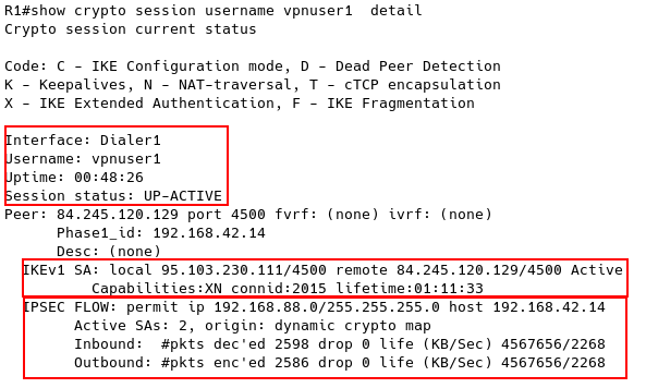
Figure 7 - Checking crypto session for Xauth
- Interface: Dialer1 - the VPN tunnel is using the Dialer1 interface.
- Username: vpnuser1 - the username used for authentication.
- Uptime: 00:48:26 - the tunnel has been active for 48 minutes and 26 seconds.
- Session status: UP-ACTIVE - successfully established and functioning IPSec tunnel.
- Peer: 84.245.120.129 port 4500 - the IP address and port of the remote peer (GreenBow Ipsec Celint) that R1 is connected to.
- Local/Remote Address: 95.103.230.111/4500 (R1) and 84.245.120.129/4500 (Peer) - These are the IP addresses and ports used for the IKE SA establishment.
- Capabilities: XN - This indicates IKEv1 exchange with NAT (Network Address Translation) traversal.
- Lifetime: 01:11:33 - The IKE SA has a remaining lifetime of 1 hour 11 minutes and 33 seconds.
- Permit IP: 192.168.88.0/24 - This specifies the allowed IP address range on the local network (R1's side) that can communicate through the tunnel.
- Remote Host: 192.168.42.14 - This is the allowed IP address on the remote network (VPN server's side) that can communicate with the local network.
- Active SAs: 2 - There are two active IPSec SAs (Security Associations), one for inbound and one for outbound traffic.
- Traffic Statistics: The output displays packet counts and rates for encrypted/decrypted traffic on both inbound and outbound directions.
Conclusion
By following these steps, you'll establish a secure IPSec VPN connection between your Cisco router and the GreenBow client. This allows authorized users on the GreenBow network to access resources on your local network securely, even when connected over the public internet.
The guide also covers verification methods to confirm a successful connection and active data flow through the tunnel. Remember to replace placeholder values like pre-shared keys and usernames with your specific configurations for enhanced security.